


Professional Manufacture PLC Hose Swager Product Making Machine
Informação básica
Modelo: SK100
Descrição do produto
Model NO.: SK100 Condition: New Automatic Grade: Automatic Product Name: Hose Swager Rubber Product Making Machine Crimping Force: 2520 Ton Rated Pressure: 31.5MPa Voltage: 220V 380V Weight: 800kg Trademark: DSG51 Origin: Tianjin, China Certification: SGS, CE, ISO Customized: Customized Structure: Vertical Crimping Range: 1/4" to 3" Ruler Precision: 0.01mm Power: 4kw Dimension: 858*;910*1550mm Dies Quantity: 10 Sets Specification: 858*; 910*1550mm HS Code: 8462919000 I. Brief introduction
The SK-100 type CNC hose crimping machine developed by our factory is suitable for hooping processing of the assembly of high pressure rubber tube, fibre pipe and plastic pipe used in industry, agriculture and fluid drive of engineering machinery. It has the advantages of wide hooping range, high precision (adopt PLC control), high degree automation, easy operation and maintenance, etc.
II. Main technical character
Hooping steel wire rubber tube inner diameter: φ4~φ51IVmm
Industry tube inner diameter: 89mm at the most
Scale precision: 0.01mm
Power: 4KW
Voltage: 380V
The maximum hooping force: 2520 tons
Rotated speed: 1440r/min
Oil pump displacement: 10ml/rad
Dimension: 858×910×1550(mm)
Weight: 800Kg
The maximum opening diameter: +68mm
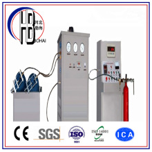
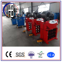
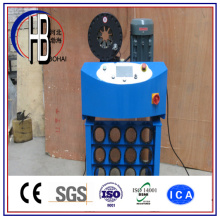
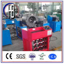
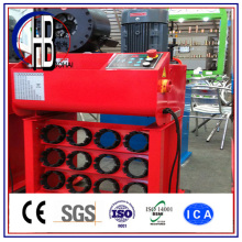
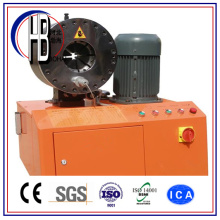
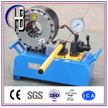
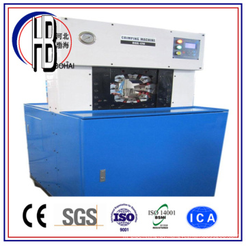
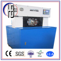
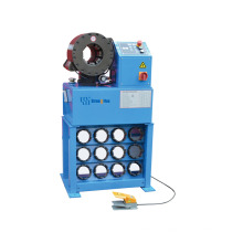
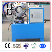
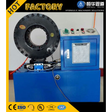
SK100 automatic hose cirmping machine photos:
III. Working principle
The oil pump driven by the electric motor outputs the hydraulic oil and push the piston in the hydraulic cylinder to make up and down reciprocating movement. Thus makes the two columns connecting with the piston drive the above board realizing up and down reciprocating movement, making the pressing block in the recess of the two up and down large square board push the die holder, and making the die holder to give rise to radial shrinkage. And in the end realize the hooping of the rubber tube by module. When the shrinkage reaches the set value on the control panel, the hooping will stop automatically. The change valve reverses automatically. The hydraulic oil enters into lower chamber of the hydraulic cylinder and drives the above board to move upward making the mould hole to enlarge. Then we can take down the hooped rubber tube assembly.
SK-100 type numerical control tube locking machine structure diagram
1. bridge rectifier 2. relay 3. time delay unit 4. pressure bar 5. down jointbar 6. joint buckle closure 7. electric motor 8. down end closure 9. hydro-cylinder 10. up jointbar 11. slide board 12. clamping plate 13. back plate 14. die holder 15. drawbar 16. up covering cap 17. electrical equipment control box 18. oil pump 19. electrical equipment box 20. hooping pressure regulating valve 21. fluid control non-return valve 22. integrated circuit block 23. mould opening pressure regulating valve 24. magnetic change valve 25. oil box 26. nut 27. lock circular nut
IV. Installing and adjustment
1. Transportation: the machine should be transported with fork-lift truck.
2. Installing: the machine should be fixed horizontally on the firm foundation and undertake ground connection treatment.
3. Oil injection: open the back cover of the machine case and inject 56 liters No. 46 antiwear hydraulic oil.
4. Electricity connection: connect the power-line with the machine prescribed electric source. Inch the electric motor and observe the rotation direction. The rotation direction of the electric motor should be consistent with arrow direction on the label of electric motor. Or after connecting the line, switch on the power switch. If the machine acts, the mould opening enlarges, this means that the rotation direction of the electric motor is right. If the machine doesn't act, it is necessary to exchange the random 2 lines of the 3 live wires.
5. Pressure adjustment: the maximum pressure of the machine system is 31.5MPa adjusted by spill valve. Adjusting clockwise the pressure increases. Adjusting anticlockwise, the pressure decreases. (When leaving the factory, the pressure has been finished adjusting. If needing to adjust the pressure of spill valve, using this equipment exceeding 31.5 MPa is strictly prohibited)
V Operation
1.Open the machine back cover, inject about 56 liters clean 46# antiwear hydraulic oil
2. Connect the power-line. Then switch on the main switch installed on the machine side. If the mould acts automatically, it means that the rotation direction of the electric motor is right. If there is no action, it means that the electric motor reverses. We should exchange the random 2 lines of the 3 live wires at the connector lug. (Caution: only after breaking the power source we can operate).
3. For the machine's initial usage, we should undertake empty load hooping 10-20 times. After observing that all parts are normal, we can use it. When using the tube locking machine in winter, we should undertake empty load movement 20-30 times in order to make the oil temperature increase a little and at the same time increase service life of the machine.
4. Switch on the main power source switch. According to the specification of the hooped rubber tube, choose the corresponding mold and install it onto the die holder. And set up C1 value( the hooping size value) and C2 value( the mold's opening degree). (for detailed C1 and C2 value taking see the technical parameter reference table on the attached sheet)
5. Put the rubber tube with joint into the lock suitable position in order to get once hooping of the whole length.
6. After pressing down the "mould closing " key or step on foot switch once, undertake hooping operation. After hooping to the set hooping size (namely reaching C1 value) and staying for 3 seconds, the mould open to the set value(namely C2 value). Take out the hooped rubber tube assembly. Check and measure the hooped pipe sleeve outer diameter with vernier caliper. If the hooped diameter is inconsistent with the parameter table, we should set up parameter again and repeat the above said operation until according with the demands.
7. During the hooping process, whenever press the "mould opening" key and don't release it, the mould will open to the set size( namely the set C2 value).
VI. The usage method of the control box
1.key mapping function
:Mould opening key. After pressing this key, the mould will open automatically.
:Mould closing key. After pressing this key once, the mould will start to execute hooping action.
:Set up key: after pressing this key, "C1="(inner diameter), "C2="(outer diameter), "C3="(0 position calibration) will be displayed in turn on the panel
:Shift key. After pressing this key, we can change in turn the place of the number preparing to be set up. For each pressing, the number place shifts one place (At this moment, the number in this place will flicker). Reciprocate in this way and change circularly.
:Number set up key: after pressing this key, the number displayed on digital tube increases from 0 to 9 in turn.
:Number set up key: after pressing this key, the number displayed on digital tube decreases from 9 to 0 in turn.
: Enter key. Only after pressing this key, we can acknowledge the corrected value.
2. Usage method
After switching on the power source switch, the machine is reset. The tube locking machine will automatically look for the initial position until it stops. The value displayed on the display at this moment is the increased value of the mould opening at this moment. By pressing the "set up" key we can set up in turn the 3 numbers values of "C1=", "C2="and "C3=". After setting up one of the three above said values, we must press once the acknowledgement key to acknowledge this value. (For example if we want to set up "C1=" value, we firstly press "set up" key. At his moment the display displays "XXX.X". And the first number (namely the hundred's place) is flickering. Press the shift key and change the place of the set up number. For each pressing, the flickering number will shift backward one place. When the number at this place is flickering, we can correct this flickering number. Through pressing "+"or "-"theses two keys we can correct this value. After finishing setting up from hundred's place to the place behind the decimal point, press the acknowledgement key and then we can confirm the "C1=" value. The set up methods of "C2="and "C3="are the same as "C1=". (Please pay attention to that: the "C3=" value, namely the 0 position calibration value, has been set up when leaving the factory. Please don't change randomly. This means that each time when "C3=" value is displayed, don't set up it. Only we need to do is to press the set up key once. After setting up the values of "C1=" and "C2=", we can start hooping.
3. Hooping reduction formula
C1=nominal pipe sleeve outer diameter (after hooping)-chosen mould inner diameter.
C2=the maximum diameter of the nut of the rubber tube assembly -the inner diameter of mould + interval value (1-5 optional)
VII. Matters needing attention
1. When hooping, place the joint into the mould center as far as possible. Don't push down on the hexagon nut.
2. Each time after working, we need to make the inner diameter of eight blocks die holder increase to 30-50mm. Thus makes the spring under relaxation condition when not working and prolong the spring's service life greatly.
3. Avoid the tools and other extraneous matter entering into lock.
4. When working don't put your hand into the lock in order to make sure of the personal safety. When repairing, we need to break the power source.
5. Each time after finishing the hooping, the mould will open automatically. During the process of the opening of the mould, if press the "mould opening" key and don't release it, the inner hole of the mould will open all along until it cannot open any more. (Note: when usual using, don't make the inner hole of the mould open fully.)
6. The function of the time delay unit is to adjust the time difference between two-position, two-way unload magnetic valve and three-position, five-way change magnetic valve and thus makes the machine run normally. When leaving the factory, this time delay unit has been adjusted to the optimal position. Don't adjust randomly. Otherwise maybe abnormal situation will occur.
7. When setting up the values of mould opening and mould closing, as long as "C3" is displayed on the display screen, please don't press the key of mould opening or mould closing. Otherwise maybe the electronic ruler will be damaged. The C3 value is the value needing to be set up when undertaking 0 position calibrations. Usually it needn't to be set up. (Namely when C3 value is displayed on the display, we need to press the "set up" key to skip over this value and don't set up it. We mustn't press acknowledgement key.)
8. This equipment is mainly suitable for the steel wire rubber tube assembly of 2 inches and within 2 inches or the industry used tube of more than 2 inches.
VIII. Maintenance
We should often check the hydraulic oil in the oil box. If finding that the oil quantity is not adequate, supplement in time the hydraulic oil. After the oil liquid is polluted, we need to filter or replace it, otherwise may cause the magnetic valve core to be blocked, machine action to get out of control and the workpiece to be damaged.
The hooping parts should keep inside clean to avoid, during the processing, miscellany entering into friction surface through the gap among the moulds and thus affecting the normal usage. Clean out in time the miscellany in the mould body brought into when hooping the joint. And often inject 30#-40# machinery oils into the contact surface between die holder and pressing block with oil gun to keep lubricating. Between die holder and pressing block it should keep lubricating. (Oil injection method: press set up key. When "C3=" is displayed on the display, press down the mould closing key and the caliber of mould will decrease until the four filter holes on the back plate coincide with the four oil cup openings installed on the large board. At this time we can use oil gun gun mouthpiece to aim at the oil cup to inject oil until the oil is full. At this position the lubricating oil should be injected once or twice everyday.). The place between the above board and back plate, slide board and clamping plate should be lubricated with oil injection using engine oil pot. (Oil injection method: take down the up covering cap. Along the gap between all the above said parts and the large board, pour into lubricating oil. And make reciprocating movement 2-3 times.). Add lubricating oil once every 2 working days.
IX. Commitment
Since the purchase day, within half a year, we guarantee to repair the malfunction of the machine. During the guarantee period, we will repair (replace if necessary) all the parts malfunctions free of charge. For the damage caused by improper use or accident, it doesn't belong to the free repair range.
X. Malfunction removal
Packing list
Besides the 14 sets of standard moulds, we give you as an additional present the mould with inner diameter of 100mm. If this mould is damaged, it is not within the free replacement range.
Note: if you need other specification mould, you can have one made to order. (You need to pay for the corresponding mould fee)
Hooping Reduction Formula
C1=nominal pipe sleeve outer diameter (after hooping)-chosen mould inner diameter.
C2=the maximum diameter of the nut of the rubber tube assembly -the inner diameter of mould + interval value (1-5 optional)
The SK-100 type CNC hose crimping machine developed by our factory is suitable for hooping processing of the assembly of high pressure rubber tube, fibre pipe and plastic pipe used in industry, agriculture and fluid drive of engineering machinery. It has the advantages of wide hooping range, high precision (adopt PLC control), high degree automation, easy operation and maintenance, etc.
II. Main technical character
Hooping steel wire rubber tube inner diameter: φ4~φ51IVmm
Industry tube inner diameter: 89mm at the most
Scale precision: 0.01mm
Power: 4KW
Voltage: 380V
The maximum hooping force: 2520 tons
Rotated speed: 1440r/min
Oil pump displacement: 10ml/rad
Dimension: 858×910×1550(mm)
Weight: 800Kg
The maximum opening diameter: +68mm
SK100 automatic hose cirmping machine photos:
III. Working principle
The oil pump driven by the electric motor outputs the hydraulic oil and push the piston in the hydraulic cylinder to make up and down reciprocating movement. Thus makes the two columns connecting with the piston drive the above board realizing up and down reciprocating movement, making the pressing block in the recess of the two up and down large square board push the die holder, and making the die holder to give rise to radial shrinkage. And in the end realize the hooping of the rubber tube by module. When the shrinkage reaches the set value on the control panel, the hooping will stop automatically. The change valve reverses automatically. The hydraulic oil enters into lower chamber of the hydraulic cylinder and drives the above board to move upward making the mould hole to enlarge. Then we can take down the hooped rubber tube assembly.
SK-100 type numerical control tube locking machine structure diagram
1. bridge rectifier 2. relay 3. time delay unit 4. pressure bar 5. down jointbar 6. joint buckle closure 7. electric motor 8. down end closure 9. hydro-cylinder 10. up jointbar 11. slide board 12. clamping plate 13. back plate 14. die holder 15. drawbar 16. up covering cap 17. electrical equipment control box 18. oil pump 19. electrical equipment box 20. hooping pressure regulating valve 21. fluid control non-return valve 22. integrated circuit block 23. mould opening pressure regulating valve 24. magnetic change valve 25. oil box 26. nut 27. lock circular nut
IV. Installing and adjustment
1. Transportation: the machine should be transported with fork-lift truck.
2. Installing: the machine should be fixed horizontally on the firm foundation and undertake ground connection treatment.
3. Oil injection: open the back cover of the machine case and inject 56 liters No. 46 antiwear hydraulic oil.
4. Electricity connection: connect the power-line with the machine prescribed electric source. Inch the electric motor and observe the rotation direction. The rotation direction of the electric motor should be consistent with arrow direction on the label of electric motor. Or after connecting the line, switch on the power switch. If the machine acts, the mould opening enlarges, this means that the rotation direction of the electric motor is right. If the machine doesn't act, it is necessary to exchange the random 2 lines of the 3 live wires.
5. Pressure adjustment: the maximum pressure of the machine system is 31.5MPa adjusted by spill valve. Adjusting clockwise the pressure increases. Adjusting anticlockwise, the pressure decreases. (When leaving the factory, the pressure has been finished adjusting. If needing to adjust the pressure of spill valve, using this equipment exceeding 31.5 MPa is strictly prohibited)
V Operation
1.Open the machine back cover, inject about 56 liters clean 46# antiwear hydraulic oil
2. Connect the power-line. Then switch on the main switch installed on the machine side. If the mould acts automatically, it means that the rotation direction of the electric motor is right. If there is no action, it means that the electric motor reverses. We should exchange the random 2 lines of the 3 live wires at the connector lug. (Caution: only after breaking the power source we can operate).
3. For the machine's initial usage, we should undertake empty load hooping 10-20 times. After observing that all parts are normal, we can use it. When using the tube locking machine in winter, we should undertake empty load movement 20-30 times in order to make the oil temperature increase a little and at the same time increase service life of the machine.
4. Switch on the main power source switch. According to the specification of the hooped rubber tube, choose the corresponding mold and install it onto the die holder. And set up C1 value( the hooping size value) and C2 value( the mold's opening degree). (for detailed C1 and C2 value taking see the technical parameter reference table on the attached sheet)
5. Put the rubber tube with joint into the lock suitable position in order to get once hooping of the whole length.
6. After pressing down the "mould closing " key or step on foot switch once, undertake hooping operation. After hooping to the set hooping size (namely reaching C1 value) and staying for 3 seconds, the mould open to the set value(namely C2 value). Take out the hooped rubber tube assembly. Check and measure the hooped pipe sleeve outer diameter with vernier caliper. If the hooped diameter is inconsistent with the parameter table, we should set up parameter again and repeat the above said operation until according with the demands.
7. During the hooping process, whenever press the "mould opening" key and don't release it, the mould will open to the set size( namely the set C2 value).
VI. The usage method of the control box
1.key mapping function
:Mould opening key. After pressing this key, the mould will open automatically.
:Mould closing key. After pressing this key once, the mould will start to execute hooping action.
:Set up key: after pressing this key, "C1="(inner diameter), "C2="(outer diameter), "C3="(0 position calibration) will be displayed in turn on the panel
:Shift key. After pressing this key, we can change in turn the place of the number preparing to be set up. For each pressing, the number place shifts one place (At this moment, the number in this place will flicker). Reciprocate in this way and change circularly.
:Number set up key: after pressing this key, the number displayed on digital tube increases from 0 to 9 in turn.
:Number set up key: after pressing this key, the number displayed on digital tube decreases from 9 to 0 in turn.
: Enter key. Only after pressing this key, we can acknowledge the corrected value.
2. Usage method
After switching on the power source switch, the machine is reset. The tube locking machine will automatically look for the initial position until it stops. The value displayed on the display at this moment is the increased value of the mould opening at this moment. By pressing the "set up" key we can set up in turn the 3 numbers values of "C1=", "C2="and "C3=". After setting up one of the three above said values, we must press once the acknowledgement key to acknowledge this value. (For example if we want to set up "C1=" value, we firstly press "set up" key. At his moment the display displays "XXX.X". And the first number (namely the hundred's place) is flickering. Press the shift key and change the place of the set up number. For each pressing, the flickering number will shift backward one place. When the number at this place is flickering, we can correct this flickering number. Through pressing "+"or "-"theses two keys we can correct this value. After finishing setting up from hundred's place to the place behind the decimal point, press the acknowledgement key and then we can confirm the "C1=" value. The set up methods of "C2="and "C3="are the same as "C1=". (Please pay attention to that: the "C3=" value, namely the 0 position calibration value, has been set up when leaving the factory. Please don't change randomly. This means that each time when "C3=" value is displayed, don't set up it. Only we need to do is to press the set up key once. After setting up the values of "C1=" and "C2=", we can start hooping.
3. Hooping reduction formula
C1=nominal pipe sleeve outer diameter (after hooping)-chosen mould inner diameter.
C2=the maximum diameter of the nut of the rubber tube assembly -the inner diameter of mould + interval value (1-5 optional)
VII. Matters needing attention
1. When hooping, place the joint into the mould center as far as possible. Don't push down on the hexagon nut.
2. Each time after working, we need to make the inner diameter of eight blocks die holder increase to 30-50mm. Thus makes the spring under relaxation condition when not working and prolong the spring's service life greatly.
3. Avoid the tools and other extraneous matter entering into lock.
4. When working don't put your hand into the lock in order to make sure of the personal safety. When repairing, we need to break the power source.
5. Each time after finishing the hooping, the mould will open automatically. During the process of the opening of the mould, if press the "mould opening" key and don't release it, the inner hole of the mould will open all along until it cannot open any more. (Note: when usual using, don't make the inner hole of the mould open fully.)
6. The function of the time delay unit is to adjust the time difference between two-position, two-way unload magnetic valve and three-position, five-way change magnetic valve and thus makes the machine run normally. When leaving the factory, this time delay unit has been adjusted to the optimal position. Don't adjust randomly. Otherwise maybe abnormal situation will occur.
7. When setting up the values of mould opening and mould closing, as long as "C3" is displayed on the display screen, please don't press the key of mould opening or mould closing. Otherwise maybe the electronic ruler will be damaged. The C3 value is the value needing to be set up when undertaking 0 position calibrations. Usually it needn't to be set up. (Namely when C3 value is displayed on the display, we need to press the "set up" key to skip over this value and don't set up it. We mustn't press acknowledgement key.)
8. This equipment is mainly suitable for the steel wire rubber tube assembly of 2 inches and within 2 inches or the industry used tube of more than 2 inches.
VIII. Maintenance
We should often check the hydraulic oil in the oil box. If finding that the oil quantity is not adequate, supplement in time the hydraulic oil. After the oil liquid is polluted, we need to filter or replace it, otherwise may cause the magnetic valve core to be blocked, machine action to get out of control and the workpiece to be damaged.
The hooping parts should keep inside clean to avoid, during the processing, miscellany entering into friction surface through the gap among the moulds and thus affecting the normal usage. Clean out in time the miscellany in the mould body brought into when hooping the joint. And often inject 30#-40# machinery oils into the contact surface between die holder and pressing block with oil gun to keep lubricating. Between die holder and pressing block it should keep lubricating. (Oil injection method: press set up key. When "C3=" is displayed on the display, press down the mould closing key and the caliber of mould will decrease until the four filter holes on the back plate coincide with the four oil cup openings installed on the large board. At this time we can use oil gun gun mouthpiece to aim at the oil cup to inject oil until the oil is full. At this position the lubricating oil should be injected once or twice everyday.). The place between the above board and back plate, slide board and clamping plate should be lubricated with oil injection using engine oil pot. (Oil injection method: take down the up covering cap. Along the gap between all the above said parts and the large board, pour into lubricating oil. And make reciprocating movement 2-3 times.). Add lubricating oil once every 2 working days.
IX. Commitment
Since the purchase day, within half a year, we guarantee to repair the malfunction of the machine. During the guarantee period, we will repair (replace if necessary) all the parts malfunctions free of charge. For the damage caused by improper use or accident, it doesn't belong to the free repair range.
X. Malfunction removal
| Malfunction content | Malfunction reason | Removal method |
| the machine doesn't act | Oil is not injected into the oil box | Injection according to the request |
| The rotation direction of the electric motor is wrong | Adjust two phase lines | |
| The trouble of the electrical equipment | Check and repair the electrical equipment | |
| Doesn't hoop | the electronic ruler wire disconnects | Connect the electronic ruler wire again |
| The system pressure is very low | Adjust the hooping pressure regulating valve | |
| The trouble of the electrical equipment | Check and repair the electric circuit | |
| The mould doesn't open | the pressure of mould opening is very low | Adjust the mould opening pressure regulating valve |
| The trouble of the electrical equipment | Check and repair the electric circuit | |
| The noise is loud | The installing is not firm | Horizontal firm installing |
| The hydraulic oil is very dirty | Filter or replace | |
| The oil filter is blocked | Clean the oil filter with gasoline | |
| The piston creep | The screw on the clamping plate is screwed too tightly | Screw off the screw properly |
| The lubrication is bad | Smear butter onto the working inclined plane of die holder | |
| Oil leaks | The joint is not screwed tightly. | Screw up the oil pipe joint |
| The seal washer is damaged | Replace the seal washer |
Packing list
| Name | Quantity |
| Principal machine | 1 |
| Mould | 14 |
| Certificate of quality | 1 |
| Technical manual | 1 |
Besides the 14 sets of standard moulds, we give you as an additional present the mould with inner diameter of 100mm. If this mould is damaged, it is not within the free replacement range.
Note: if you need other specification mould, you can have one made to order. (You need to pay for the corresponding mould fee)
| Sk-100 type hose crimping machine technical parameter reference table | ||||||||||||||||
| Nominal rubber tube inner diameter φ | Nominal pipe sleeve outer diameter before hooping φ | Nominal pipe sleeve outer diameter after hooping φ | the inner diameter of the needed mould φ | Hooping size value (C1)mm | ||||||||||||
| φ4 | 12 | 12 | 13 | 14 | 10 | 10 | 10 | 11 | 9 | 9 | 9 | 9 | 1 | 1 | 1 | 2 |
| φ6 | 19 | 21 | 23 | 25 | 16 | 18 | 20 | 22 | 13 | 16 | 19 | 22 | 3 | 2 | 1 | 0 |
| φ8 | 21 | 23 | 25 | 27 | 18 | 20 | 22 | 24 | 16 | 19 | 22 | 22 | 2 | 1 | 0 | 2 |
| φ10 | 23 | 25 | 27 | 29 | 20 | 22 | 24 | 26 | 19 | 22 | 22 | 26 | 1 | 0 | 2 | 0 |
| φ13 | 28 | 31 | 33 | 35 | 24 | 27 | 29 | 31 | 22 | 26 | 26 | 30 | 2 | 1 | 3 | 1 |
| φ16 | 31 | 34 | 36 | 38 | 27 | 30 | 32 | 34 | 26 | 30 | 30 | 30 | 1 | 0 | 2 | 4 |
| φ19 | 34 | 37 | 39 | 41 | 30 | 33 | 35 | 37 | 30 | 30 | 30 | 30 | 0 | 3 | 5 | 7 |
| φ22 | 38 | 40 | 42 | 45 | 34 | 36 | 38 | 41 | 30 | 30 | 38 | 38 | 4 | 6 | 0 | 3 |
| φ25 | 40 | 43 | 45 | 47 | 36 | 39 | 41 | 43 | 30 | 38 | 38 | 38 | 6 | 1 | 0 | 5 |
| φ32 | 49 | 51 | 53 | 55 | 46 | 47 | 49 | 51 | 45 | 45 | 45 | 45 | 1 | 8 | 4 | 6 |
| φ38 | 55 | 57 | 59 | 61 | 51 | 53 | 55 | 57 | 45 | 45 | 55 | 55 | 6 | 8 | 0 | 2 |
| φ51 | 68 | 70 | 72 | 74 | 64 | 66 | 68 | 70 | 55 | 65 | 65 | 65 | 9 | 1 | 3 | 5 |
| φ64 | 86 | 88 | 90 | 82 | 84 | 85 | 75 | 75 | 75 | 7 | 9 | 10 | ||||
| φ76 | 103 | 105 | 99 | 101 | 88 | 96 | 11 | 6 | ||||||||
| φ89 | 107 | 102 | 100 | 2 | ||||||||||||
C1=nominal pipe sleeve outer diameter (after hooping)-chosen mould inner diameter.
C2=the maximum diameter of the nut of the rubber tube assembly -the inner diameter of mould + interval value (1-5 optional)
Grupo de Produto : Máquina de friso da mangueira
Premium Related Products


outros produtos


produtos quentes
P20HP Manual 1/4 "a 2" máquina de crimpagem de mangueira até 2 "mangueira com grande desconto300 ~ 1500rpm Piso Moagem e Polimento Máquina Power Tools / Diamond Hand Polishing para venda!Preços de perfuratrizes montados em perfuradores de lagartasCe de alta qualidade nova chegada máquina de friso de mangueiraFlanges de tubos de aço inoxidável forjados OEMEncaixe de tubulação da mangueira da carcaça de bronze da fonte da fábrica com melhor preçoMáquina de friso da mangueira hidráulica automática do fornecedor de ChinaMáquina de enchimento de extintor de incêndio ABC Dry Powder for ExtinguisherChina PLC Quick Change Tools Máquina de crimpagem de mangueiraMáquina de crimpagem hidráulica de mangueira hidráulica Fin Best Quality FinnTubo de aço inoxidável de carbono soldado e sem costura ASTM A53200 Máquina de perfuração de poços de água de lagartasBoa qualidade Water Rock Soil Drilling Rig MachineASME B 16.47 Flange Forjada em Aço InoxidávelMáquina de crimpagem hidráulica de mangueiras de desempenho confiávelAcabamento de tubo de cotovelo de raio longo de 90 graus de 90 °